Wednesday, November 30, 2011
Sunday, November 13, 2011

This is a must share with all you out there in 1933 Chevrolet land. The "Chevrolet 1933 Passenger Car Engineering Features" book. This is filled with nearly 100 pages of details and specs.
http://www.gmheritagecenter.com/gm-heritage-archive/docs/Chevrolet/1933-Chevrolet.pdf
It downloadable and usable.
This find made my day.
Saturday, November 12, 2011

This is the clutch fork. There is a wear of .88 with the new bearing at .9. I'll fill this area in the fork with weld. And grind it down to the original diameter. It will interesting to see how much travel will return. The two hole that are in the fork next to the wear area must be for a spring holder or something. I'd like to know if there is a part I need to find.
Friday, November 11, 2011
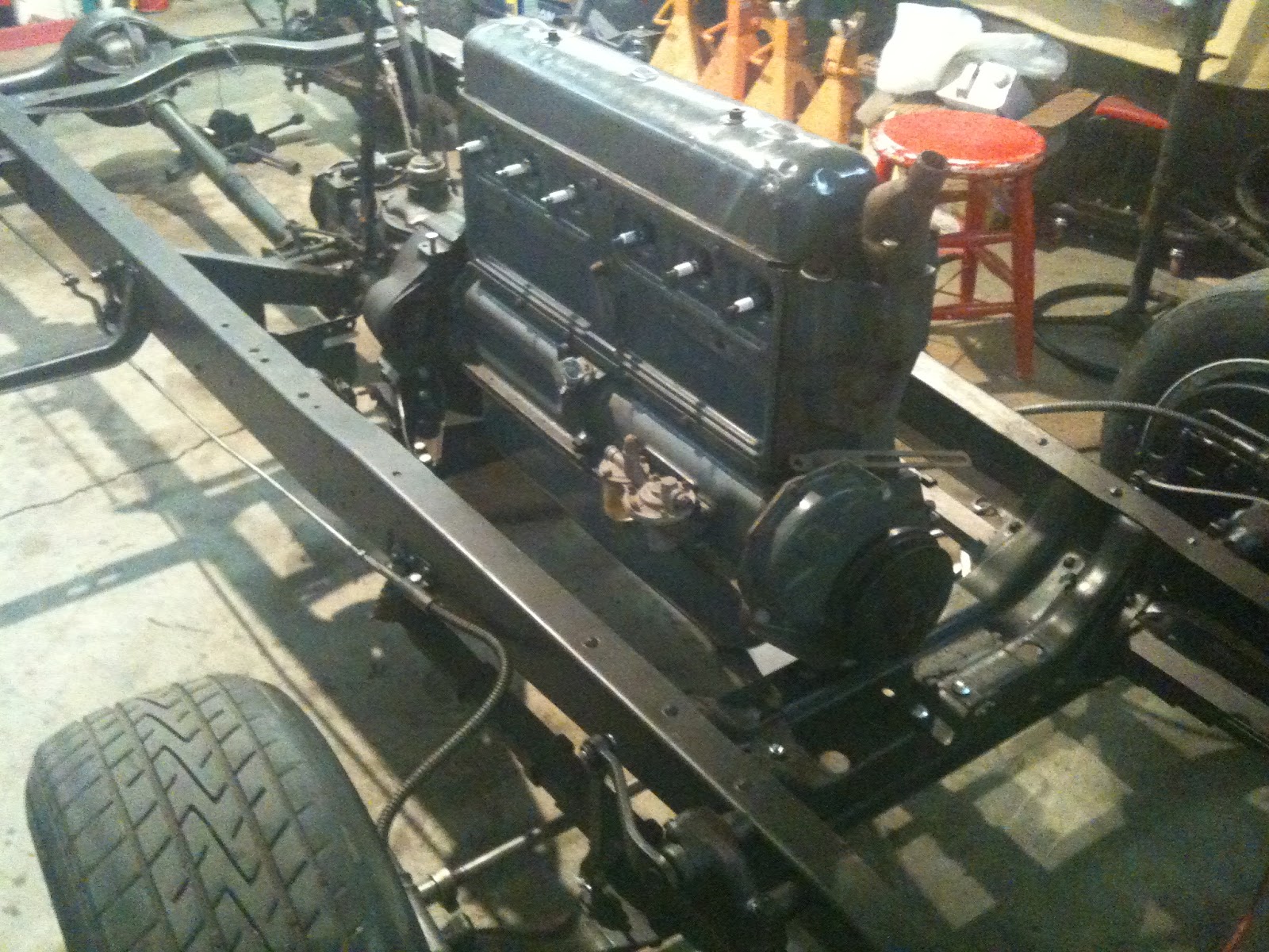
Here is the engine in the chassis. The front motor mount is now on the underside of the frame cross member. This allowed the side and transmission mounts to fit into place. There is still a problem with the front motor mount. The bracket on the front of the engine for mounting with the motor mount rests on the frame. The inner cast parts of the front motor mount do not reaching up far enough to cause a clearance between the frame and the bracket mount on the engine. I have inserted a strong piece of machine shop belting between the frame and motor mount to cause some separation. This can't be the right way to solve this problem. Open for all suggestions.
Don
Tuesday, November 8, 2011


This is the part of the clutch pedal that is used to adjust the travel of the clutch. This picture shows the amount of wear in the hole. This area was filled with weld and reground down to a tighter fit on the clutch fork. I forgot to take a picture of the filled and reground hole size. Maybe I can include that picture the next time I take everything apart again.

This picture shows the bushing being driven by hammer into the brake bushing hole. The bushing is about 2/3 of the way inserted. Above the tool I made is another rod that was made to fit inside the "bushing removal tool". This second tool was the one hammered on. The old bushing came right out, and new bushings were hammered in place with no damage. I used this method because I don't own a press.

Sunday, November 6, 2011

Friday, November 4, 2011
I finally got the engine to fit pretty well. There is still some tweaking that needs to be completed. As all of you know other duties have taken me away for the project for the moment. Has anyone else ever felt that restoring a car is like the dime movies we use to go to on Saturday morning. The movies would go to some exciting point and stop. You had to spend the whole week waiting to get back to the movies to see what happened. Then it would start all over again. To be continued.
Saturday, October 15, 2011


When I started installing the engine it looked like nothing was going to fit. I had just the engine and the bell housing during the first attempt at placing the engine. No matter what I did it just didn't fit. I'll back up a bit. When I bought the car the engine was in a box not the car. I was told it was a 33 engine that had been rebuilt. However the person who had done the work died. The fellow I had purchased the car from said the wife told him that her husband had rebuilt the engine. So you know I was a little suspect about the engine. Now it looked like my suspicions were true. So I started checking engine numbers etc. so I could do some research. I also got on line to the VCCA and stated the problems I was having. One member stated that the engine was a 33 however it was a truck engine. This gave me a little hope. Next I installed the transmission etc. This way I could check the alignment and fit.After several hours work it was apparent that the engine etc. was going to fit. The side motor mounts still do not line up correctly. Maybe they are the mounts for a standard car. If they can't be changed some adapters will have to be made. The pictures just before this one show the misfit.

This looks like a pretty big jump, and it is. The seals for the wheels came in so I was able to clean and grease the wheel bearings, insert the wheel seals, and assemble the front wheels. I didn't include any pictures of that process, because it's what you have already seen. The next step is to test install the engine and transmission to confirm proper fit. It is so great to have a rolling chassis again.
Tuesday, October 11, 2011

One of the interesting challenges of restoration is often the small stuff. This is a picture of one of the brake return springs. I have looked through all the supplies that I know of as well as eBay. So far I can't find this spring. So for now this part of my restoration is at a stand still. I probably work on the engine for a while until I can find springs.
Monday, October 10, 2011

Sunday, October 9, 2011

Friday, October 7, 2011

Wednesday, September 28, 2011

This is one of the original brake linings I removed form the 33 Chevy. I Goggled WYRBAC and got nothing. The licence plate on the car was a 1956 CA. If anyone knows about the age/vintage of the brake linings, I would like to know. Just clues to try and establish the last time this car was on the road. Also maybe how many miles might be on the car.
Sunday, September 25, 2011


This photo shows the completion of today's work. All the parts on the right front brake have been refurbished and installed. This was a slow process today. The new rivet brake lining can be seen on the top of the brake shoe. A reminder, If you double click on any of the pictures you will bring up a larger picture.


After the parts are cleaned the rust can be stopped my encapsulating the rust. This is the chemical I prefer to use. It changes the rust and turns the metal black. It should dry for 24 hours before a paint is applied. To keep the parts free and moving well inside the brake Drum, this is the only treatment I will use.

A power wire brush will be used to remove the rust form the part. There is sand blasting, chemical baths, and dip tanks to remove rust. This process is slower but is much cheaper. I should have had my gloves on for this picture. It's hard to work the camera and do this at the same time. Also be ready to get very dirty.

This is the first in a series of pictures to show how to refurbish a brake shoe in a early 30's car. This is also for the younger set out there that hasn't seen what makes an old car tick. This is a brake shoe. The working part of a car that has brake Drums an not Disk brakes. Another difference is that the brakes are mechanical and not hydraulic. The brakes are controlled by the movement of steel rods not liquid pressure.
This picture shows the condition of the brake shoe at the beginning of the process. If one were working on a much newer car, what makes a part go, no go, is much different. This car has a top speed of maybe 55mph.

Safety and other considerations. When working on old cars one need to consider safety. Paints have lead, brake shoes have asbestos, many types of metal particles, paints and other chemicals are and where used of all kinds. I thought I'd throw in this picture of me in my safety garb. If I was in all white, I look as if I'd come from Star Wars. One of the considerations for doing this blog is to pass on the idea that almost any young man can work on a car project. You don't have to spend a fortune to do a 100 point show car. I'm doing what might be called a refurbish rather than a restoration. In a 100 point restoration the car comes out brand new or even better. What I'm doing is a ground up "refurbish". This evolves taking almost everything apart, checking for wear, cleaning, removing and preventing rust, making sure the parts are serviceable, and finally reconditioning. Also parts are replaced when they are beyond service. The end results will be an original car that has been refurbished. Finally I will include pictures and explanations when I feel that manuals and other available information is not complete for someone new to the hobby.
Saturday, September 24, 2011


Today was another big step. The front axle, springs and shakes were installed. It actually starting to look like a car chassis. I'll be working on the installation of the right brake parts next. I'll also work on the left brake parts. However I won't be able to install the parts until the new spindle arrives. From my last check on eBay it may be a while. The main rod of the steering will have to be straightened. The local machine show can do that the best. They have straighten thing for me before. And did a great job. One of the great things about living in a small town is you can get little jobs like this completed. In the big city they wouldn't even look at such a small job.
Friday, September 23, 2011

Backing plate for the right brake has been cleaned. Two small 1" inch cracks were located in the backing plate, welded, ground and then the backing plate was treated and painted. The plate that holds the brake shoes is also in this picture after being cleaned treated and painted. I spent most of the day on these two parts. The left spindle, not shown in this picture, will have to be replaced. The spindle threads were badly stripped.


Tuesday, September 20, 2011


The middle bearing surface on this mounting bracket for the mechanical brake control rod is badly worn. It allowed the shaft to wobble and make the brakes on the right side of the car almost nonadjustable. So my thinking was that I needed to increase the surface to carry the load. I decided to get some oil impregnated bearing stock and make a new bearing surface.
Sunday, September 18, 2011


After many hours the brakes were completely dismantled, then cleaned with a wire brush on a drill. After cleaning all parts were cleaned with solvent and painted. Time was then spent making sure that all parts moved freely. New brake linings were installed with new rivets. A new brake spring was located and replaced. New oil seals were also installed. The axles were cleaned and surfaces. They are now ready for installation.


Subscribe to:
Posts (Atom)